The Octosonar board interfaces up to eight HC-SR04 ultrasonic sensors to Arduino using the I2C bus and one interrupt pin.
The software to use on the Arduino is the Octosonar library. This page describes hardware installation.
Recommended Tools and Stuff
- up to 8 HC-SR04 sensors
- up to 8 F-F 4 pin jumper wires
- one 8 pin and one 2 pin jumper wire to your controller. One female end for the Octosonar, the other end to match your controllers. OR FeatherWing headers for Feather controllers.
- four #4 or 3mm standoffs and screws.
- Arduino compatible controller
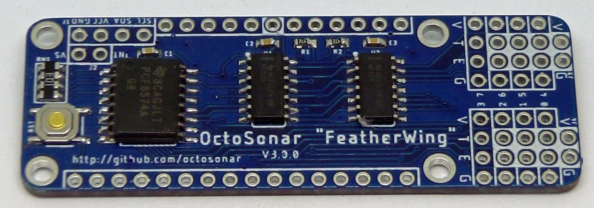
Board Details V3 “FeatherWing” Compatible
Dimensions
- Size: FeatherWing footprint extended 0.5″ on one end
- Hole Spacing: FeatherWing footprint
- Hole diameter: 0.12″ – #4 screw (3mm)


Hookup Instructions: Feather controller.
If you are using a Feather board, solder on your preferred FeatherWing headers (not included) and plug the OctoSonar into your Feather board as you would any other Wing.
Note the following:
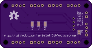
- I2C address is set to 0x38. This can be changed via solder jumpers on the back.
- 4.7k I2C pullup resistors are on the board. They may be disconnected by cutting solder jumpers on the back.
- the product uses one hardware interrupt pin in addition to I2C. This is connected to the third GPIO pin (count from BAT) which corresponds to Arduino pin 2 on the Feather 328P. This is highlighted in white. Other boards may need a different pin. This can be changed by cutting and soldering jumpers on the back.
- HC-SR04 sensors require a 5V supply, while the the Feather standard is 3.3V. There are now HC-SR04-P sensors which can run on 3.3V or 5V, apparently with shorter range for 3.3V. On the Octosonar the sensor voltage is called VS. By default this is connected to the USB power pin. If your Feather is not running off a 5V supply, this will be dead. To run the whole system on 3.3V (e.g. battery) you need to cut jumper V2 to disconnect VS from USB, and connect jumper V1 which connect VS to 3.3V/VCC, and use HC-SR04-P sensors.
- the OctoSonar includes a reset button for Feather users.
Hookup Instructions: wired connections.
The OctoSonar is an I2C bus device and you will connect it to the I2C bus on your controller. Please refer to your controller documentation for which pin is which on your controller. In addition you will need to connect one hardware interrupt pin and possibly an additional power connection.

- connect the SDA, SCL, VCC and GND pins as you would for any I2C device. If your controller is a 3.3V device, VCC will be 3.3V – if it is a 5V device it will be 5V.
- 4.7k I2C pullups are included on the board. These may be disconnected by cutting solder jumpers on the back.
- I2C address is 0x38 and can be changed via solder jumpers
- The board takes power from VCC, but the sensors take a separate power feed from the VS pin. This allows us to use 5V HC-SR04 sensors with a 3.3V controller. HC-SR04-P sensors can operate at 3.3V or 5V with more range at 5V. If your desired VS voltage is the same as VCC, you can avoid the extra wire and join VS to VCC with the V1 jumper. If you connect V1, always cut V2 – this will protect Feather boards if you use them with the OctoSonar in future.
- connect a hardware interrupt pin to the INT pin. See your controller documentation for appropriate pins to use. Pin 2 on the Arduino Uno works.
- the reset button on the board is only functional when the board is installed as a FeatherWing

Hookup Instructions: sensors.
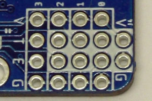

Each sensor connects with 4 wires marked V, T, E and G for Voltage, Trigger, Echo and Ground. Sensors can be connected individually using 4-pin cables connected to the vertical columns of 4 pins numbered 0 thru 7 at the right of the board.
If you are mounting the sensors on my Trimount brackets, each Trimount can support 3 sensors with only two cables by sharing the V and G connections. To do this solder two 4 pin headers horizontally in the locations marked out in white. Wire two 4-pin cables to the matching locations on the Trimount bracket. This leaves one sensor location free in in the header block – you can connect another sensor there as before.
Board Details V2.1 (retired)
Dimensions
- Size: 2.5″ x 1.3″ (63.5mm x 33mm)
- Hole Spacing: 2.2″ X 1.0″ (56mm x 25.4mm)
- Hole diameter: 0.12″ – #4 screw (3mm)
- Header mounting holes are slightly staggered to assist in manual installation. While basic pin headers are included there is clearance to install locking headers if desired.
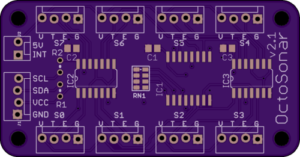
Key
- 5V supply line for HC-SR04 sensors.Connect to 5V pin on your controller or other 5V power feed. I it is a separate supply, it shouldhave the same ground as your controller.
- INT return signal to Arduino hardware interrupt pin. The library defaults to pin 2 for the Arduino Uno. For other controllers refer to your controller documentation. These are usually marked INT0, INT1, INT2 etc on pinout diagrams.
- SCL, SDA I2C bus connection to the SCL and SDA pins on the Arduino. On most recent Arduino boards (e.g. Uno R3) these are available next to the AREF pin, and are also available at another location (A5 and A4 on the Uno).
- S0, S1, ….., S7 connections to the HC-SR04 sensors. Make sure to match V,T,E,G to the VCC, TRIG, ECHO, GND on the sensors. Reversing these wires can cause damage to your components!
- VCC, GND connect these to VCC and GND on your controller.
- R1, R2 these are locations where I2C pullup resistors can be installed vertically. The I2C bus will not function without pullup resistors! Some controllers (e.g Arduino Uno) will enable their internal pullups on their end, but these are too large a resistance to work reliably. If you don’t have pullups installed elsewhere on the bus, install them here. 4.7kΩ is usually a good value for these.
- Solder jumper V1 This will connect the 5V power to the VCC power. Use this only if you have a 5V controller and VCC and 5V are the same thing. This lets you save a wire.
- Solder jumpers A0, A1, A2 These change the address of the board. The board ships with address 0x38 (56 decimal). Connecting A0 will add 1, A1 will add 2 and A2 will add 4, allowing a range from 0x38 – 0x3F (56 – 63 decimal)