The OctosonarX2 board interfaces up to sixteen HC-SR04 ultrasonic sensors to Arduino using the I2C bus and one interrupt pin.
The software to use on the Arduino is the Octosonar library. This page describes hardware installation.
Recommended Tools and Stuff
- up to 16 HC-SR04 sensors
- up to 16 F-F 4 pin jumper wires
- one 4 pin and one 2 pin jumper wire to your controller. One female end for the Octosonar, the other end to match your controllers.
- four #4 or 3mm standoffs and screws.
- Arduino compatible controller
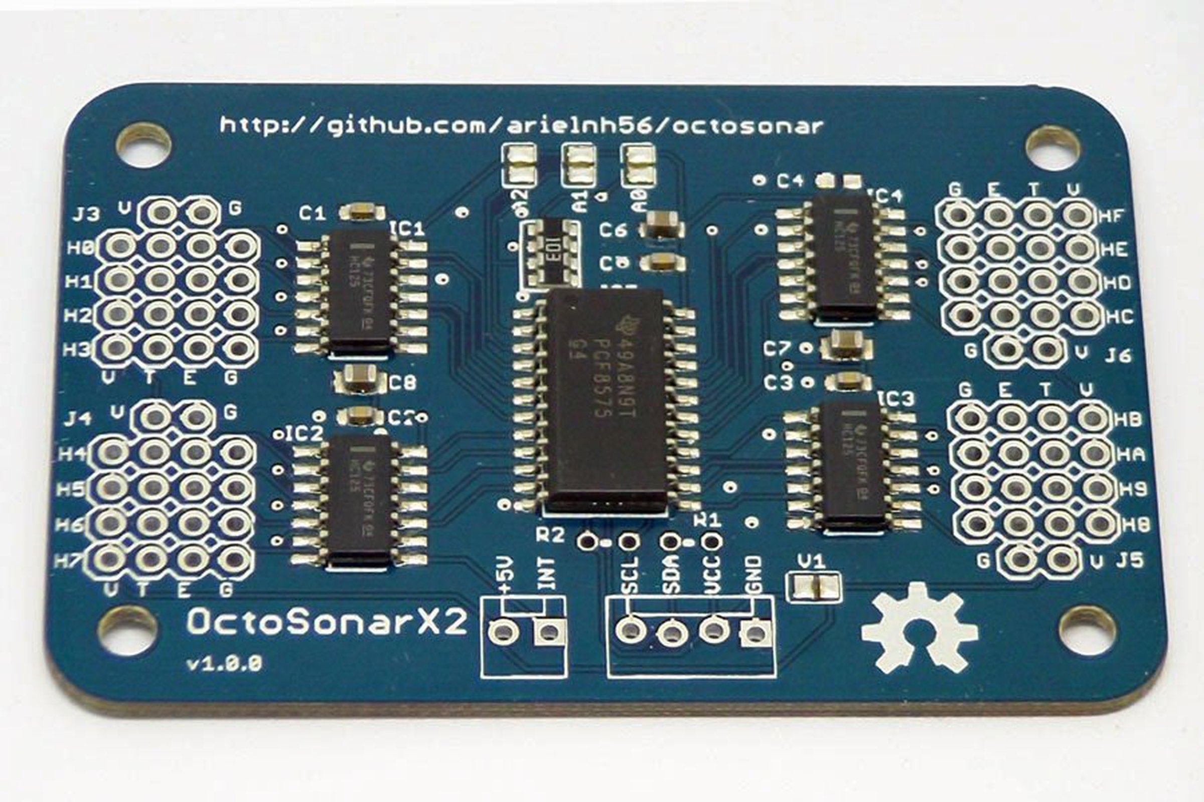
Board Details
Dimensions
- Size:
- Hole Spacing:
- Hole diameter: 0.12″ – #4 screw (3mm)
Key
- 5V supply line for HC-SR04 sensors.Connect to 5V pin on your controller or other 5V power feed. I it is a separate supply, it should have the same ground as your controller.
- INT return signal to Arduino hardware interrupt pin. The library defaults to pin 2 for the Arduino Uno. For other controllers refer to your controller documentation. These are usually marked INT0, INT1, INT2 etc on pinout diagrams.
- SCL, SDA I2C bus connection to the SCL and SDA pins on the Arduino. On most recent Arduino boards (e.g. Uno R3) these are available next to the AREF pin, and are also available at another location (A5 and A4 on the Uno).
- H0, H1, ….., HF connections to the HC-SR04 sensors. Make sure to match V,T,E,G to the VCC, TRIG, ECHO, GND on the sensors. Reversing these wires can cause damage to your components!
- V, G are additional sensor power pins to enable cable reduction when using 3 sensors mounted on a Trimount bracket.
- VCC, GND connect these to VCC and GND on your controller.
- R1, R2 these are locations where I2C pullup resistors can be installed vertically. The I2C bus will not function without pullup resistors! Some controllers (e.g Arduino Uno) will enable their internal pullups on their end, but these are too large a resistance to work reliably. If you don’t have pullups installed elsewhere on the bus, install them here. 4.7kΩ is usually a good value for these.
- Solder jumper V1 This will connect the 5V power to the VCC power. Use this only if you have a 5V controller and VCC and 5V are the same thing. This lets you save a wire.
- Solder jumpers A0, A1, A2 These change the address of the board. The board ships with address 0x20 (32 decimal). Connecting A0 will add 1, A1 will add 2 and A2 will add 4, allowing a range from 0x20 – 0x27 (32 – 39 decimal)